Testing a high speed flash means I need an extremely fast laser camera trigger. And by fast, I mean microseconds (millions of a second). Having recently finished working on Triggertrap Ada, which is the highest-performance, most feature-packed camera trigger out there, I wanted to go the opposite direction and make the absolute minimal laser trigger. I didn’t care about configurable delays or thresholds: I just cared about speed. I also decided to set myself an arbitrary cost limit of $2. I’ve clearly spent so much of the past year working obsessively to target BOM costs that I couldn’t escape it! I’m only including the cost of components, and not things like cables, breadboards or the laser pointer (or flash).
How to trigger a flash
My current testing is with a regular speedlight flash (my Olympus FL-600R), which I have connected to a Triggertrap flash adapter (TT-FA2). This is simply a way of connecting the hotshoe pins to a cable, which makes things a bit easier. The TT-FA2 has a 3.5mm stereo audio socket, and is wired so that connecting the tip and the sleeve of the plug will trigger the flash, so that’s what we’ll do. UPDATE: some people have called me out for using the expensive flash adapter. To be clear: it’s not required. I just used it because I have one and it makes the connection sturdier. You could instead use crocodile clips to connect to the flash’s foot. One in the side (the sleeve connector) and one in the centre pin. Duct tape is your friend there. You could skip the 3.5mm socket in that case too, and just connect the wires directly.
OMGLAZORZ!
At its most basic, a laser trigger is simply a laser pointed at a light sensor of some kind. When the beam is broken we complete the circuit, triggering the flash. Let’s break it down into its components.
First up is the laser itself. The main decision here is visible or infrared. Using a visible laser has the major drawback of showing up in your photos, but it has several benefits that outweigh that. First, they’re cheap and easy to buy. Second, if you’ve ever tried to align an infrared laser then you’ll appreciate being able to see the beam. Finally, visible lasers are a lot safer. You could accidentally shine an infrared laser into your eye without triggering your blink reflex, which is a recipe for toasted retinas.
Next up we need to choose the light sensor. A photoresistor is cheap but slow, while a photodiode is fast but expensive. A phototransistor works perfectly for us, and is relatively cheap and fast. Most of the ones you’ll find are sensitive to infrared light but as I’m using a red laser pointer I need one sensitive to visible light. I chose the Vishay TEPT4400 as I had a couple already.
When I started on the circuit, I assumed that I would need to enforce a minimum trigger period in order to trigger the flash. I planned to use a 555 timer to generate the trigger pulse. Luckily, before I wasted too much time on that I decided to test it. I used an Attiny45 as a pulse generator, and started with a 500 nanosecond pulse. I was pleasantly surprised that this was enough to trigger the flash, so I chucked out the 555 timer idea. Even the fastest bullet will break a laser beam for at least 10μs, so we’ll be fine.

That's what 1 microsecond looks like
I could probably trigger the flash directly with the phototransistor, but when connecting to a flash it’s a better idea to isolate the trigger circuit. I’m using an optocoupler, which is what we’re using on Triggertrap Ada, and we used in the first version of the Triggertrap Mobile Dongle. An optocoupler is simply an LED and a photodetector in a single package. When power is applied to the LED it triggers the photodetector. This means there’s no electrical connection between the flash and our trigger circuit. We can drive it in the same way as any other LED, with a current-limiting resistor (R1). Here’s the circuit.

IMPORTANT: Thanks to a couple of people on HN and Reddit for pointing out that I’ve messed up the polarity of the power supply in this schematic. The breadboard illustration is correct though.
We want the flash to trigger when the beam is broken, i.e. when the light level is low. This means we’ll use a common emitter circuit, which will take the output high when the light level drops and low when the light level rises. We want it to act as a switch, rather than having an output proportional to light level. A phototransistor can act in either mode, depending on the value of R2. 4.7KΩ works nicely for me.

Here’s the circuit on the breadboard. You’ll see that I’ve covered the phototransistor in heat-shrink. This isn’t strictly needed, and I’ve left it off the final circuit. The pin headers are just where I was connecting the probes of my scope.
For the final version I blew the real life budget by using an Adafruit Permaproto board for soldering it, because it’s convenient and I had a few lying around. You could of course use something cheaper. Stripboard in the right size should be under 20c on ebay. I also added a power indicator LED, but havn’t included that in the schematic or BOM, and removed it in the final version. I’m driving it from a 5V power supply.
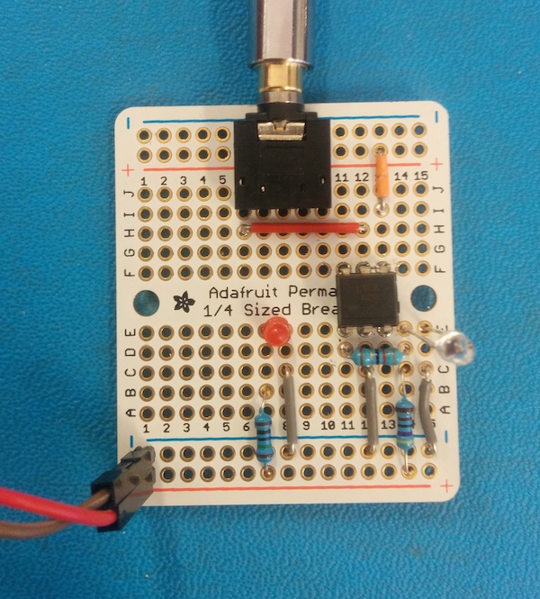
The top rails aren’t connected to power, but to the jack socket, as this was the only way I could get the socket right up to the edge of this board.

The final bill of materials. Prices via Octopart.
- TRS1: 3.5mm jack socket. Switchcraft 35RAPC4BHN2. $0.88 from Arrow.
- Q1: Phototransistor. Vishay TEPT4400. $0.25 from Avnet
- U1: Optocoupler. Vishay 4N35. $0.30 from Allied
- R1: Resistor 68Ω
- R2: Resistor 4.7KΩ
Total price $1.44 (plus a few pennies for the resistors)
Next up, taking some photos!

Here’s a photo I took of a BB fired from an air pistol. I’ve not cropped this, so you can see the laser and mirror. The sensor board is underneath, out of shot. I used a normal speedlight on lowest power, but there’s still motion blur as it’s travelling at around 400 feet per second (125 m/s).
In my next post I’ll talk about how I took this, even though I’m in an office which can’t be blacked-out. I’ll also show how to set up more interesting high speed shots where I actually start smashing things. Subscribe for free to get updates about this and other posts.
You may also like:
Vela Pop is the fastest sound trigger in the world, with a latency under 10µs. Ideal for capturing bullets and explosions, it's also happy to connect to a regular speedlight and shoot balloons and droplets. You can also hook it up to your camera for slower subjects such as wildlife...and spacecraft! It will fit in your pocket, and battery lasts for weeks.